Design
Marine & Offshore

Mid-Ocean Standing Platform for an Offshore Steel Tower

A 2.3 m split steel platform that locks around a 26-inch offshore tower: designed from site photos, released as drawings and laser-cut DXF files for fabrication.

Client
Timeline
Service
Design
Industry
Marine & Offshore
Services provided
  • Reverse engineering from site photos
  • Steel plate structure design
  • Split-joint and latch design
  • 3D CAD (SolidWorks, STEP)
  • 2D fabrication drawings & BOM
  • Laser-cut DXF files
  • Assembly animation
01 · The challenge

Problem statement

A crew platform fitted around a steel tower at sea was worn out, and there were no drawings to build a replacement. The new platform had to fit a 26-inch tower, be carried out in pieces and assembled on site, seal against the tower, drain water off the deck, and be cut from standard steel plate.

02 · The work

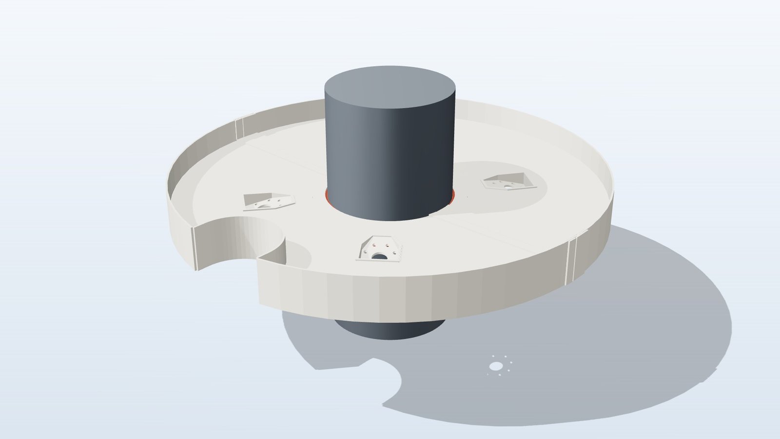
A circular standing platform that clamps around a 26-inch steel tower out at sea, giving crews a safe, drained place to stand. The platform is about 90 inches (2.3 m) across, built from laser-cut steel plate in two halves that are carried out and locked together around the tower, and sealed to it.
Assembly animation: the platform halves, inner shell, seal ring, drain boxes and support fins coming together
Platform fitted on the steel tower, render
Fitted on the 26-inch tower
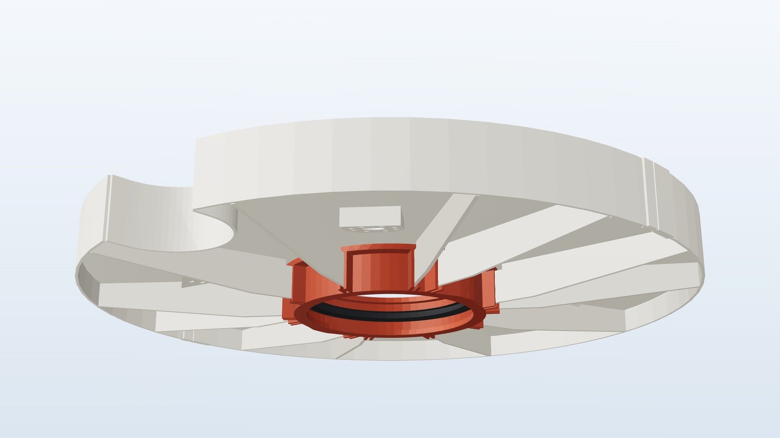
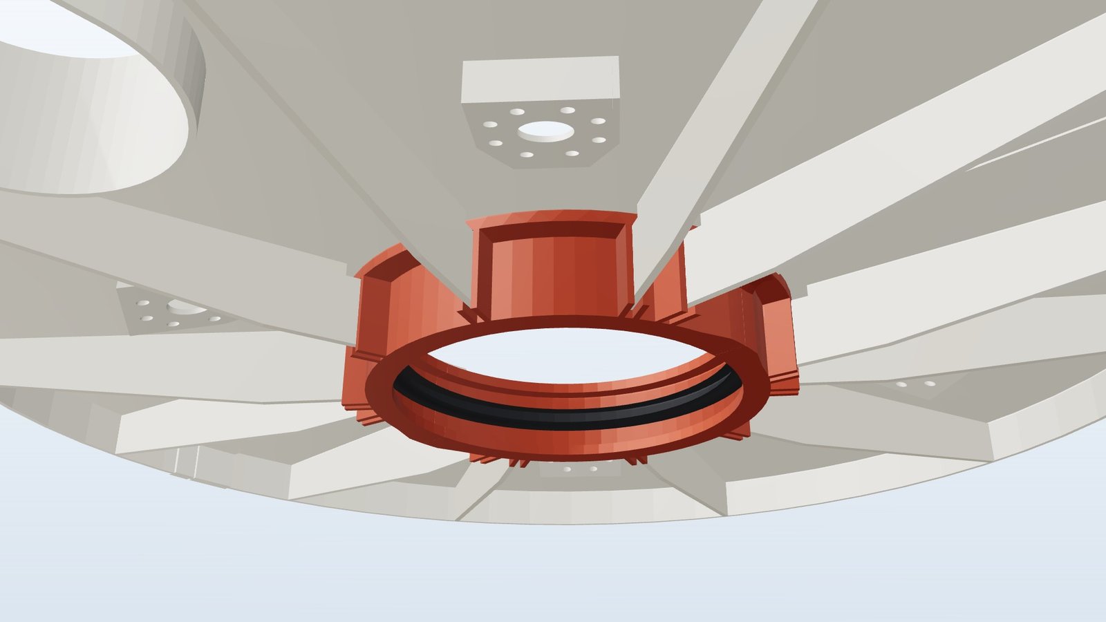
Underside detail: red inner shell, seal and fins
Underside: inner shell, seal ring and support fins

Designed from photos of an existing unit

The client had a worn platform in service but no drawings. We rebuilt the design from site photos and a handful of key dimensions, then refined it as more measurements came in from the field. Changes requested along the way, such as reducing the support dividers from nine to six per side, were built into the model.
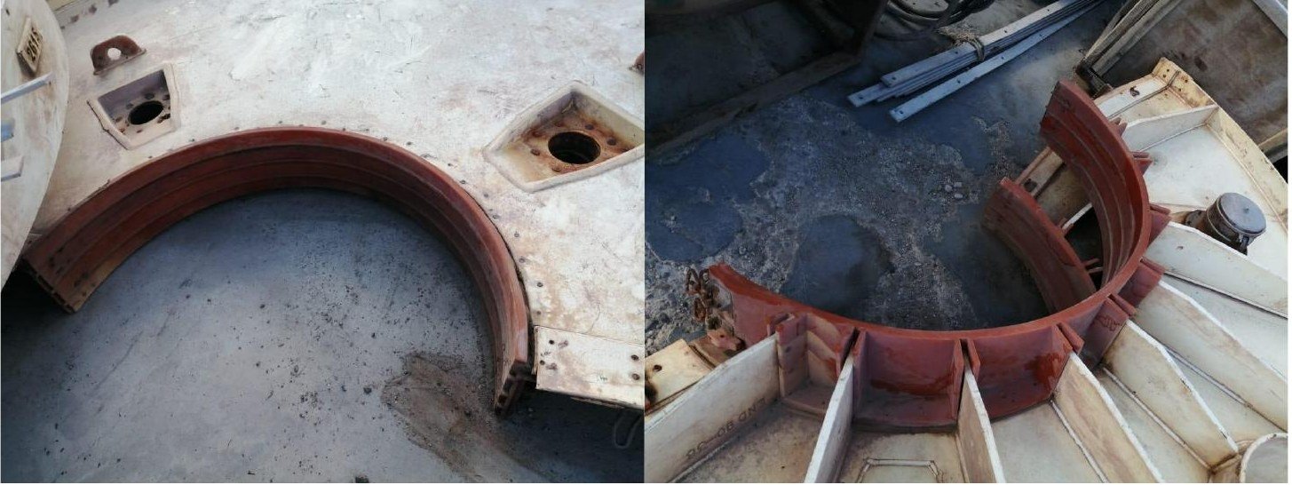
Existing platform used as reference
Reference: the existing platform, photographed on site

What we designed

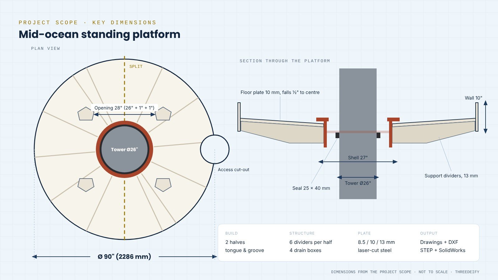
Key dimensions from the project scope
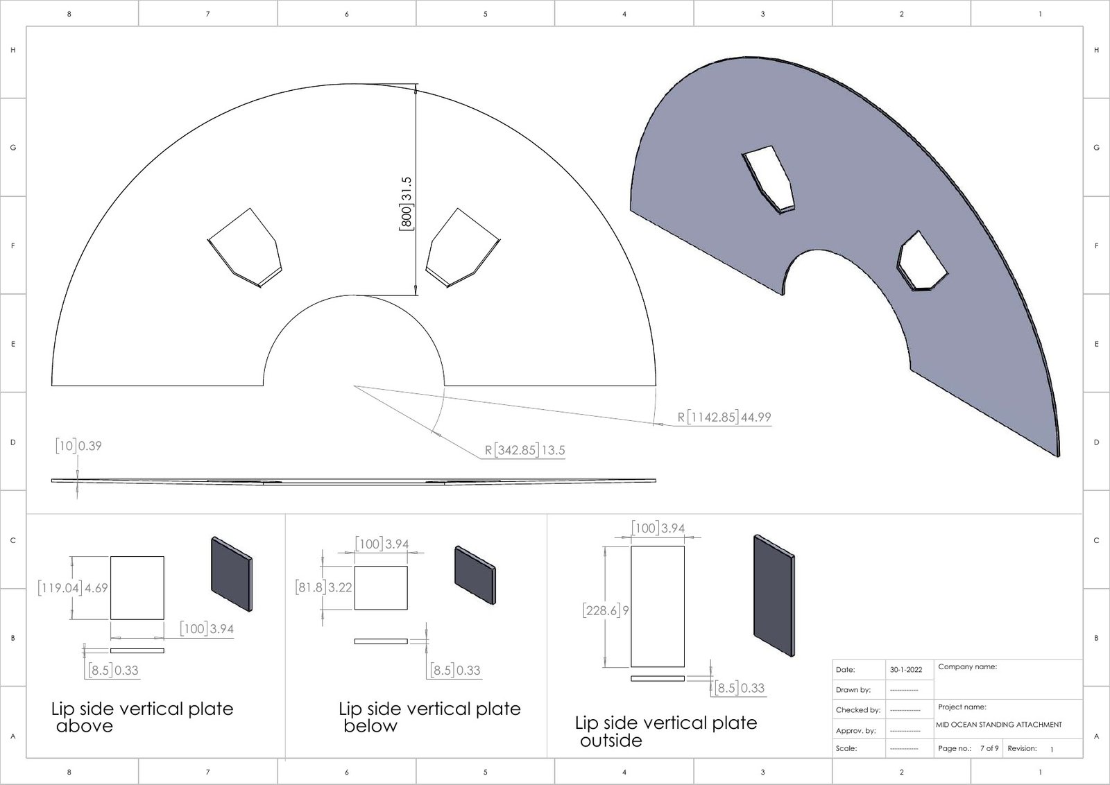
  • Floor base in two halves: 10 mm plate with a centre opening for the tower and a side cut-out for access, with a slight fall toward the drains.
  • Tongue-and-groove joints with over-centre latches: so the two halves line up and lock together on site, with room left for welding.
  • Split inner shell: a two-part ring that sits around the tower and carries the floor.
  • Seal ring: closes the gap between the platform and the 26-inch tower.
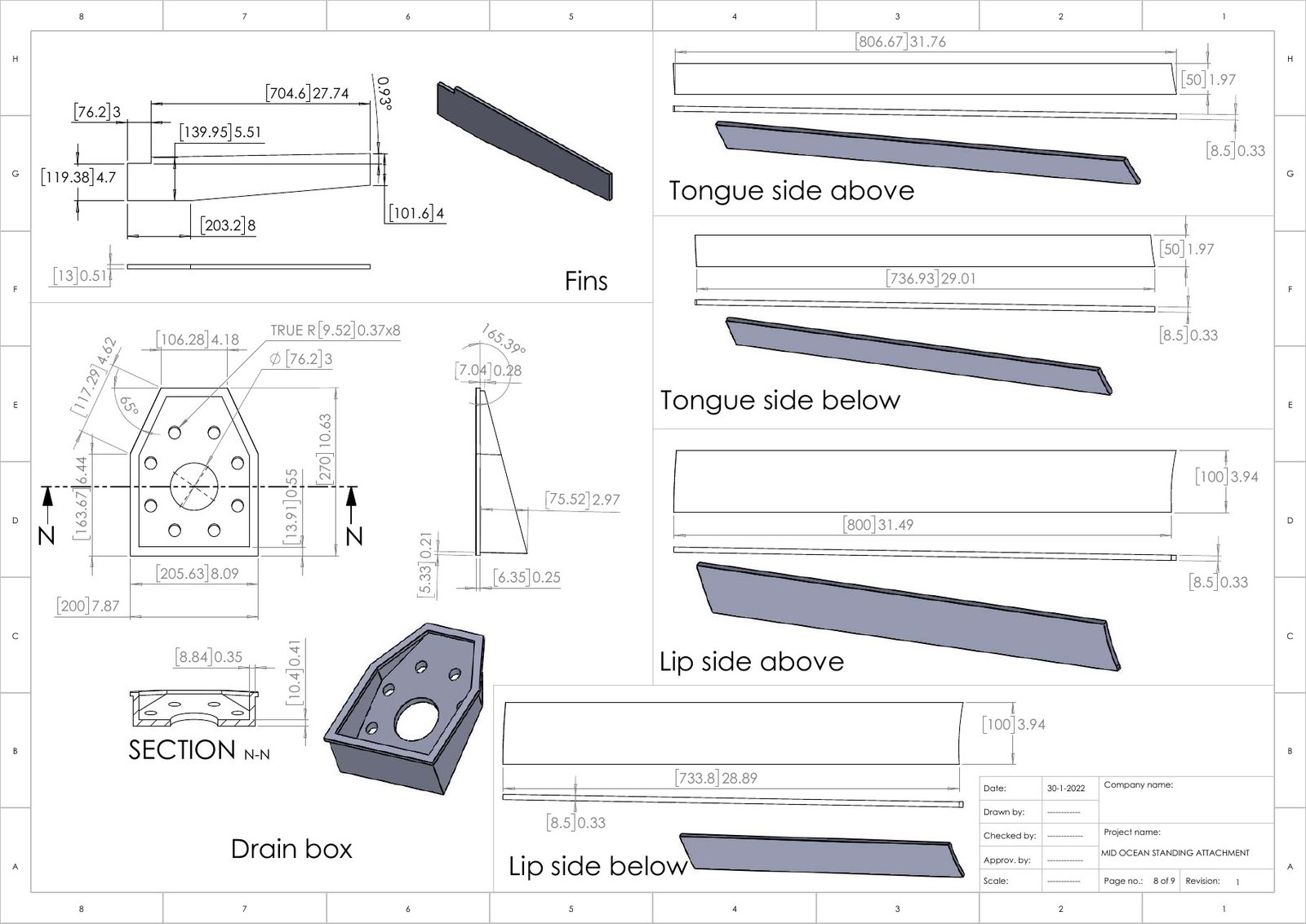
  • Drain boxes: four recessed drain inserts that let water run off the deck.
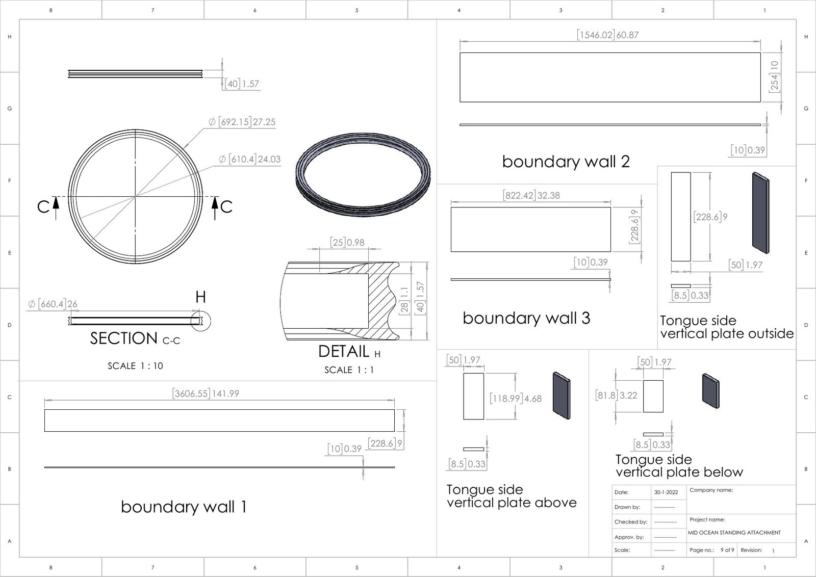
  • Support dividers and boundary wall: six radial fins per side under the floor and a perimeter wall made in four pieces.

Assembly and exploded views
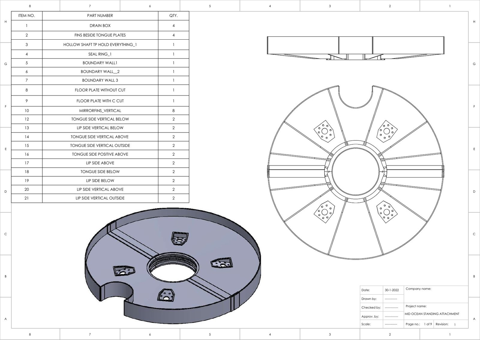
General assembly drawing with bill of materials
General assembly with bill of materials
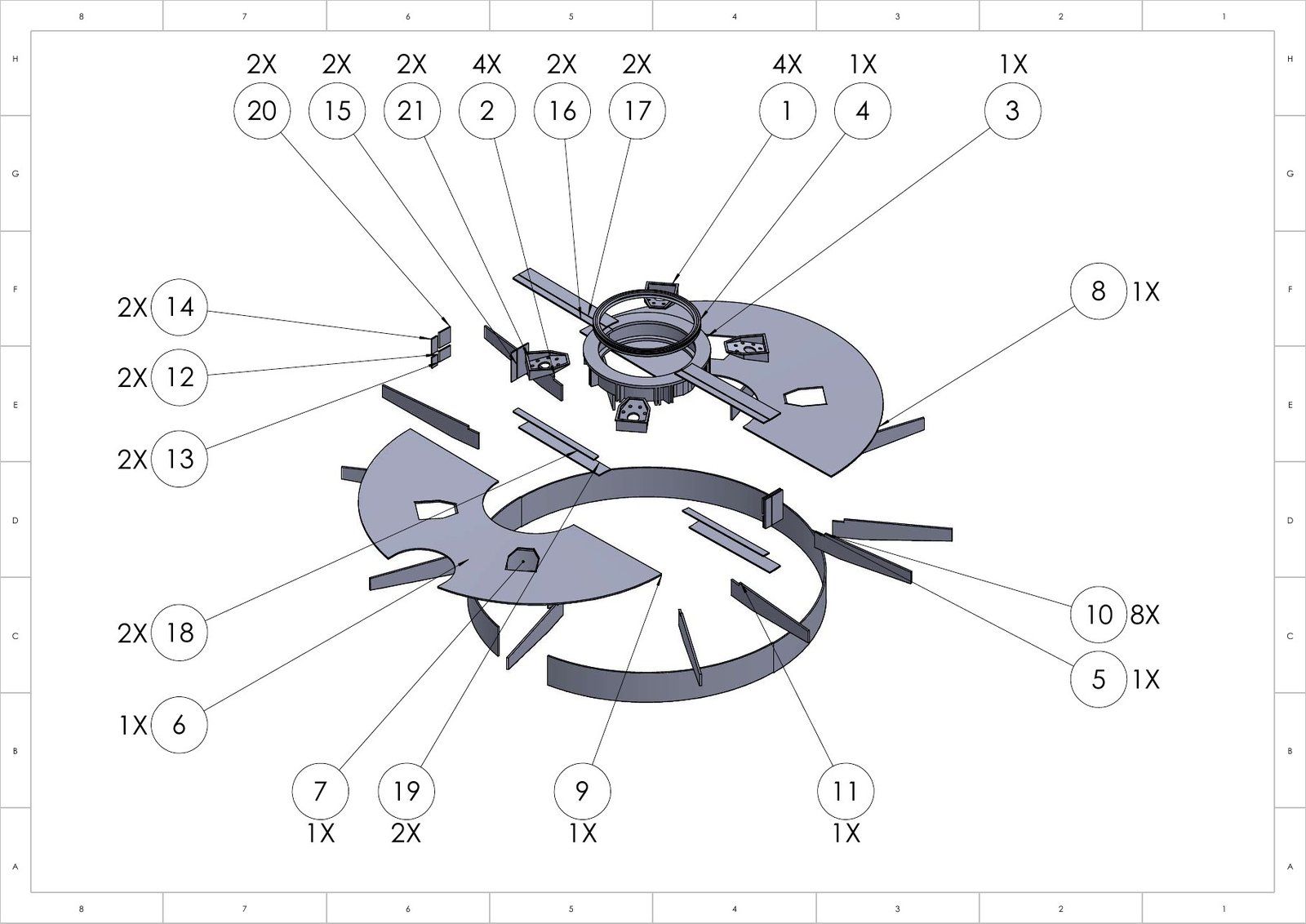
Exploded view with balloon callouts
Exploded view: 21 part types, ballooned to the BOM
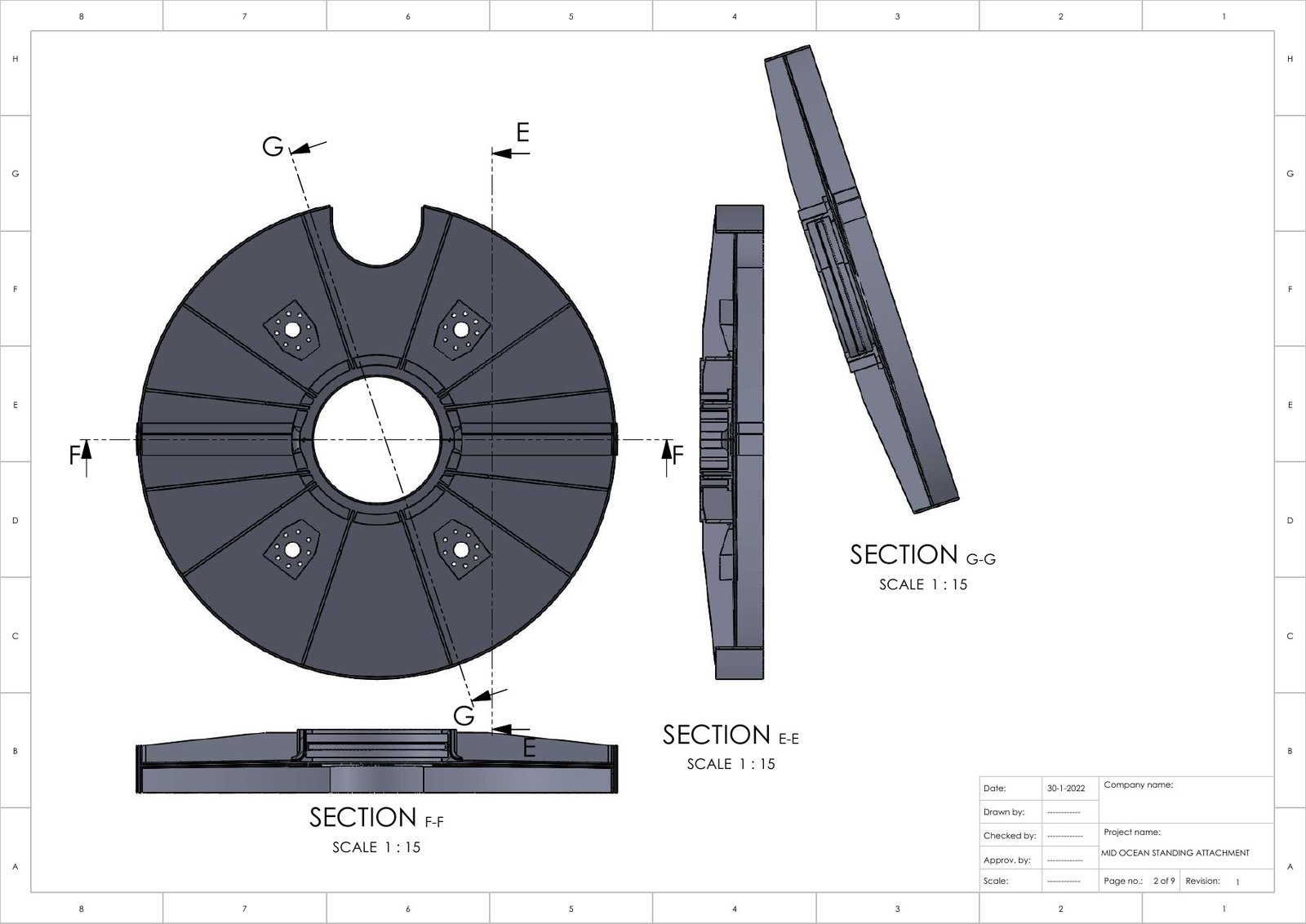
Platform sections
Sections through the platform
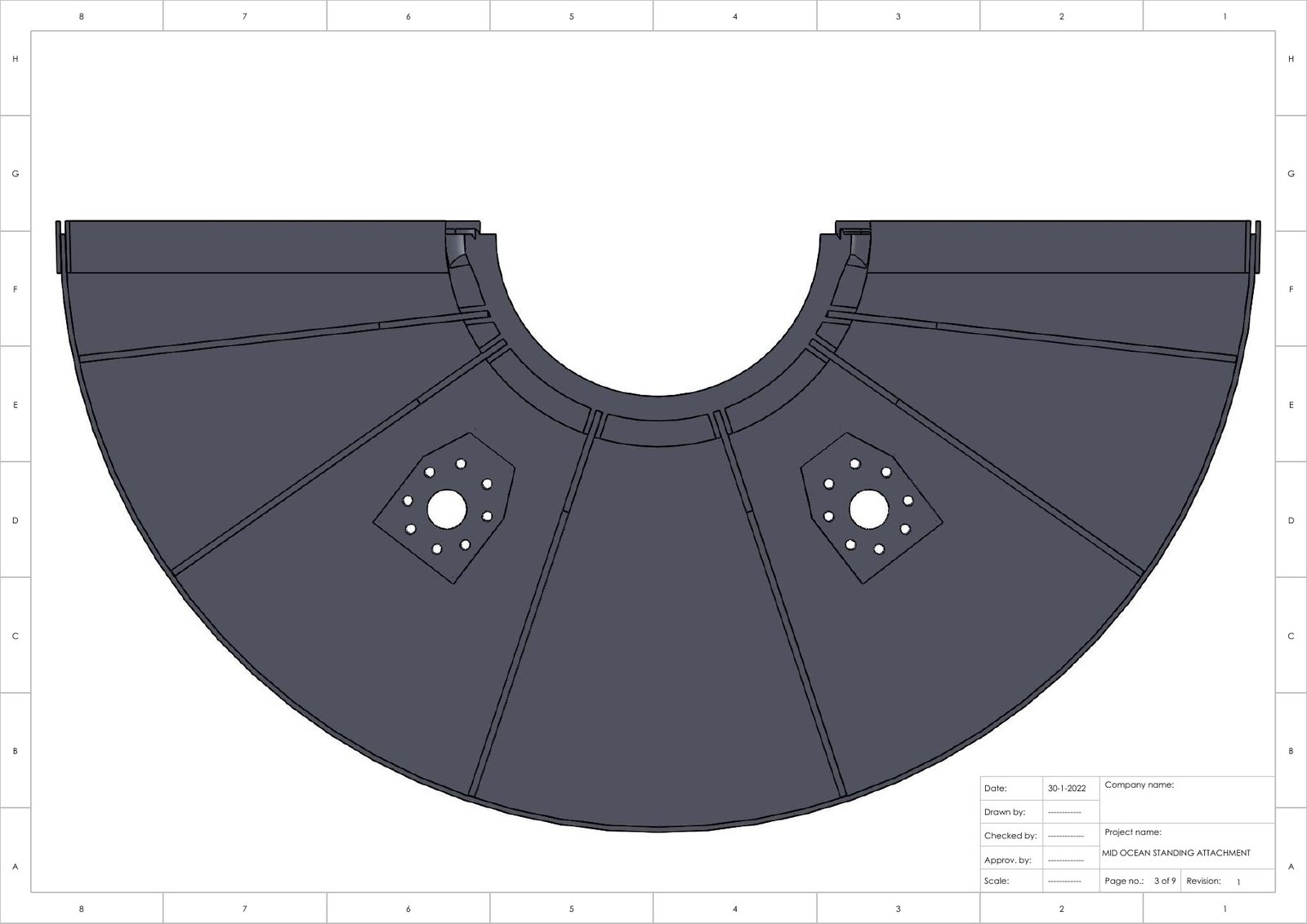
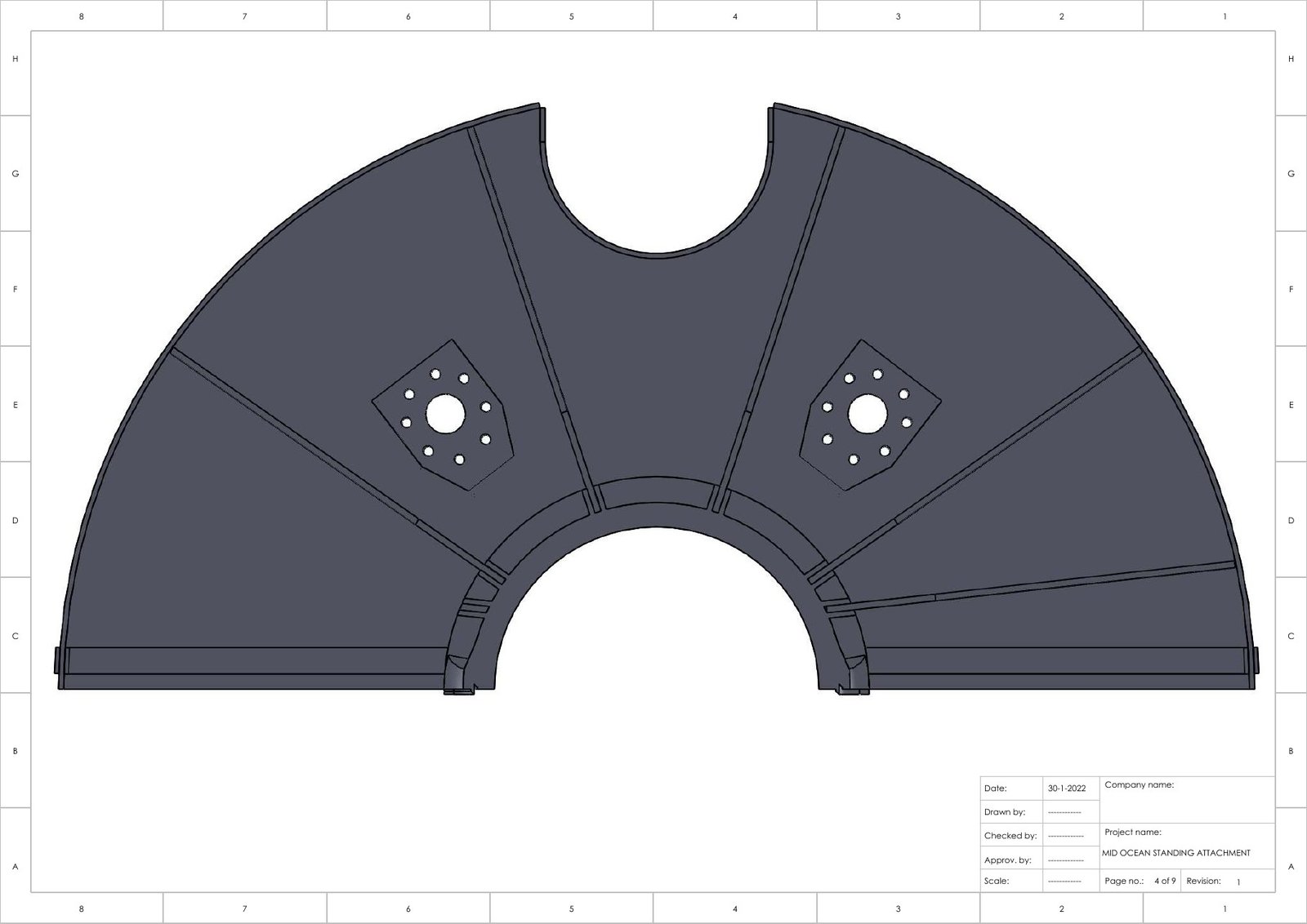
Platform half, top view
Half 1
Platform half with access cut-out
Half 2 with access cut-out

Part drawings for fabrication

Every part was released with its own drawing and a flat pattern, grouped by plate thickness (8.5, 10 and 13 mm) so the fabricator could nest and laser-cut each sheet directly from the DXF files.
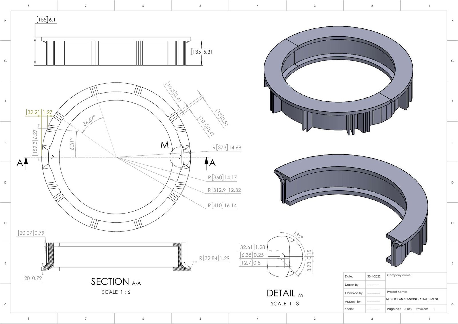
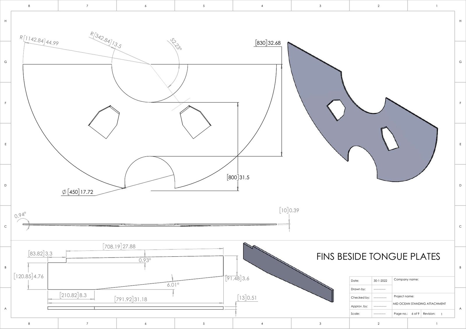
Inner shell and seal ring drawing
Inner shell and seal ring
Fins drawing
Fins beside the tongue plates
Floor plate and lip plates drawing
Floor plates and lip-side plates
Drain box and tongue plates drawing
Drain box, fins and tongue plates
Boundary wall drawings
Boundary wall pieces and vertical plates

Deliverables

  • 3D model of every part and the full assembly (SolidWorks and STEP)
  • 2D drawings of all parts and the assembly
  • DXF cut files grouped by plate thickness for laser cutting
  • Assembly animation
  • Revisions during manufacturing as field dimensions were confirmed
03 · The result

Final outcome

  • A complete, buildable design recreated from photos and a few field measurements.
  • Two halves that lock together on site with tongue-and-groove joints and over-centre latches.
  • Fabrication-ready files: drawings for every part and the assembly, a bill of materials and DXF cut files by plate thickness.
  • Updated through manufacturing as field dimensions were confirmed.
More work

Other projects

Design
Industrial Automation

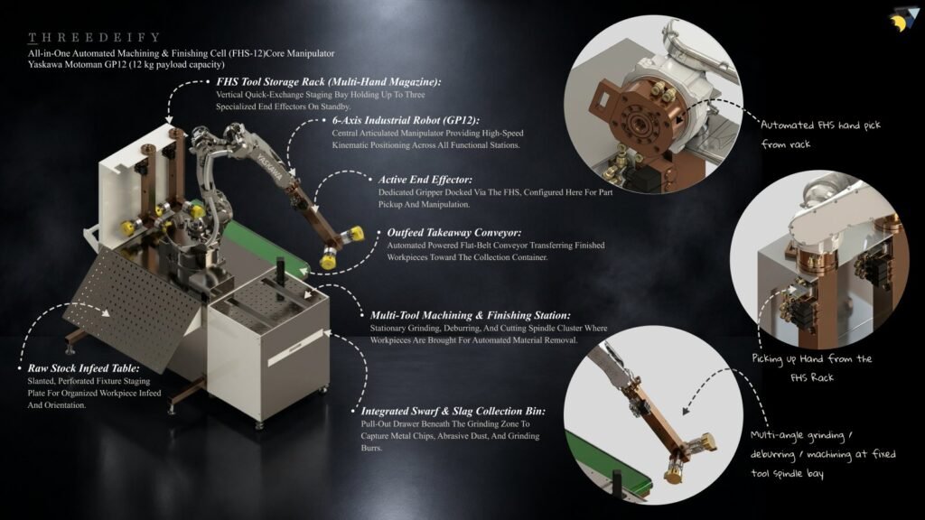
An all-in-one robotic cell where a Yaskawa GP12 swaps between specialised end effectors to load, grind, deburr and unload parts automatically.

View case study →
Design
Industrial Automation

The HFCY50 GP12 End Effector, designed for Wiswig Factory, features interchangeable jaws, ensuring adaptability for diverse machining and automation processes.

View case study →
Design
Furniture

A pet house with built-in storage: an arched den for the pet and drawers for everything the pet owns, including an integrated feeding drawer.

View case study →
Like what you see?

Let’s build your product next.

Book a free consultation and get a clear plan for your idea within one business day.