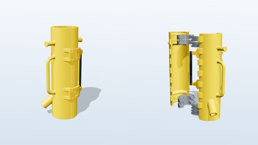
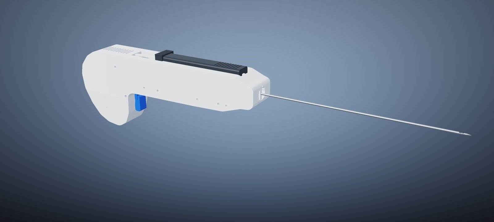
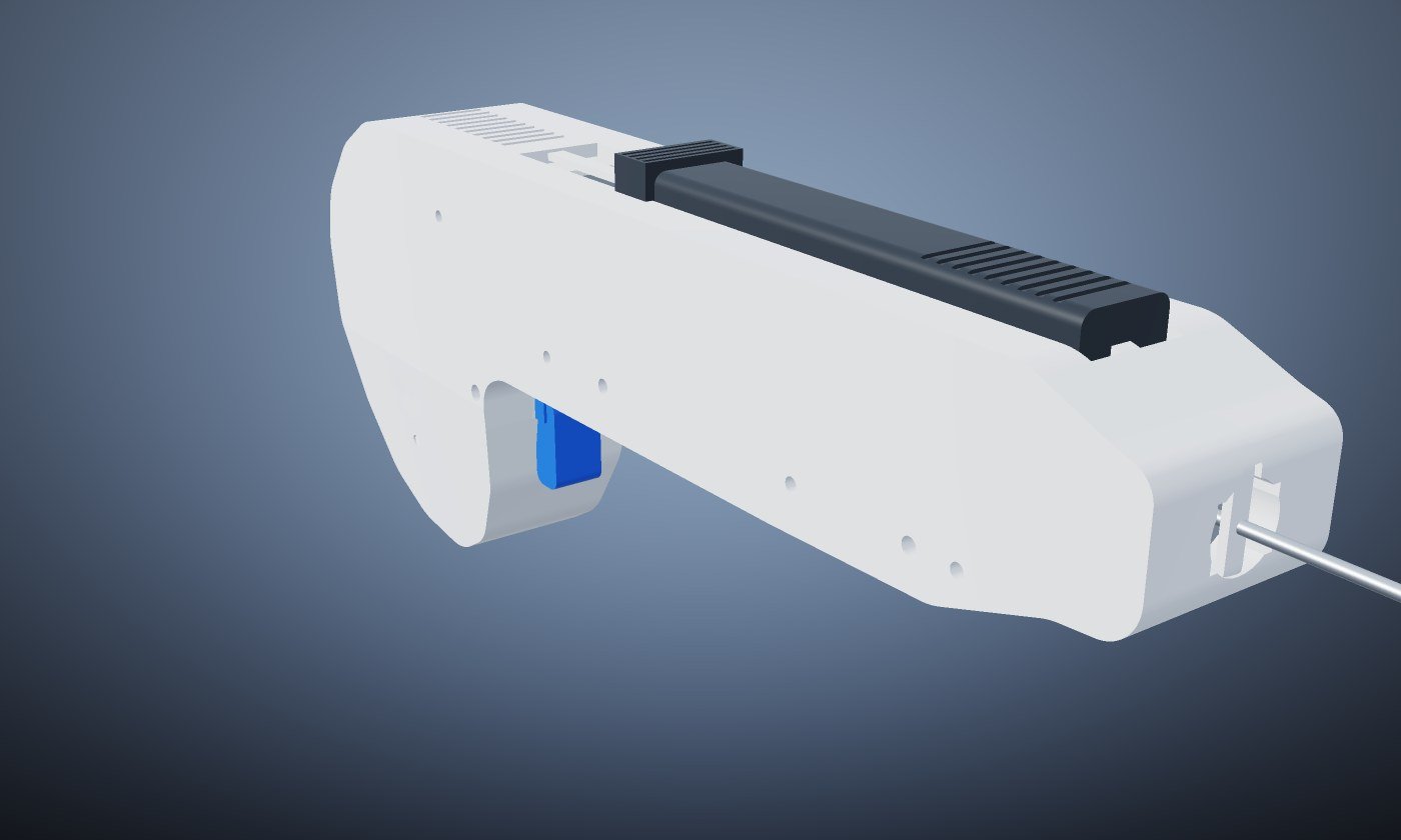
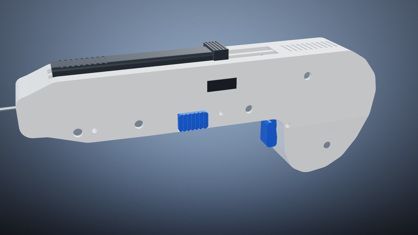
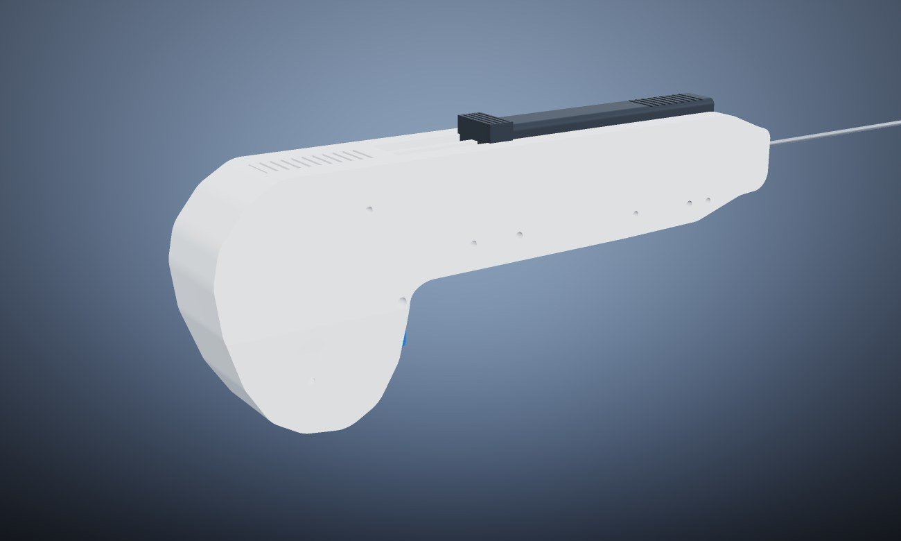
A self-initiated concept study for a reusable, spring-actuated core biopsy instrument. Threedeify took the CoreMax CB-16 from a blank sheet to a 31-part parametric assembly, a set of PBR concept renders, an ISO A1 general assembly drawing with full GD&T, and an interactive 3D presentation — every deliverable generated from one CAD source, so every dimension agrees everywhere it appears.
Concept study. Not a medical device and not for clinical use. Geometry, tolerances and timing are internally consistent and manufacturable in principle, but have not been verified by physical prototype, FEA or clinical evaluation.
The instrument at a glance
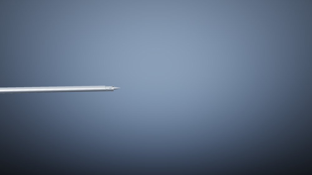
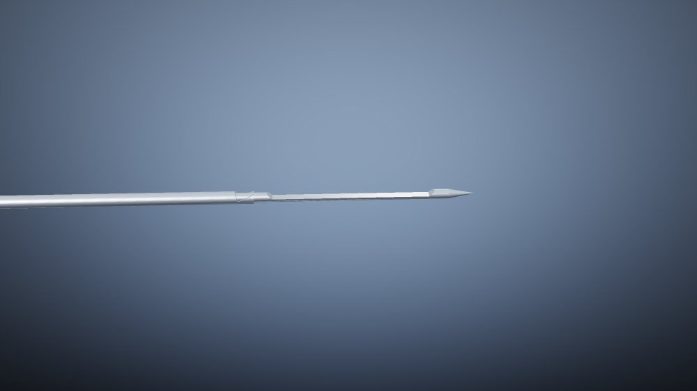
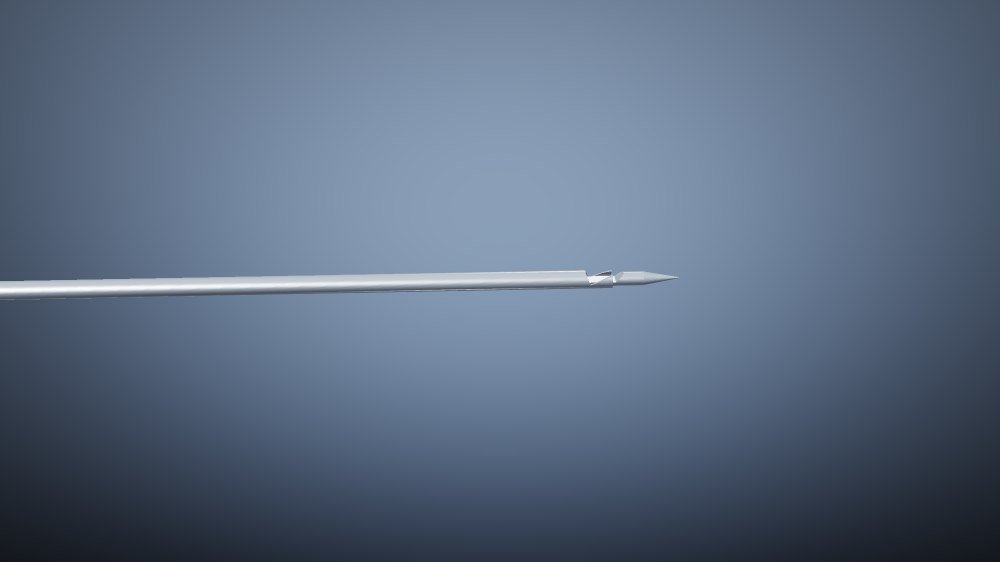
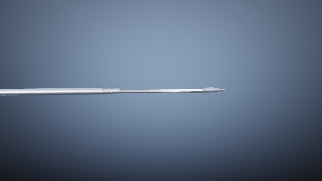
- Needle: 16G (Ø1.65 mm) × 160 mm exposed, sterile single-use dual-needle cartridge
- Specimen: 20.0 mm core, notch 0.65 mm deep, 24.6 mm³
- Firing cycle: 28 ms total, against a < 30 ms target
- Sequencing delay: 3.5 ms, set by a 0.6 mm cam stagger on the sear bar
- Throws: stylet 26.0 mm to open the notch, cannula 22.0 mm to cut
- Trigger: 18 ±3 N at 4.5 mm travel, with a positive sear-block safety
- Cocking: two-stage, 26 mm thumb-slide travel
- Envelope: 196 × 30 × 81 mm body, 362 mm overall, 118 g
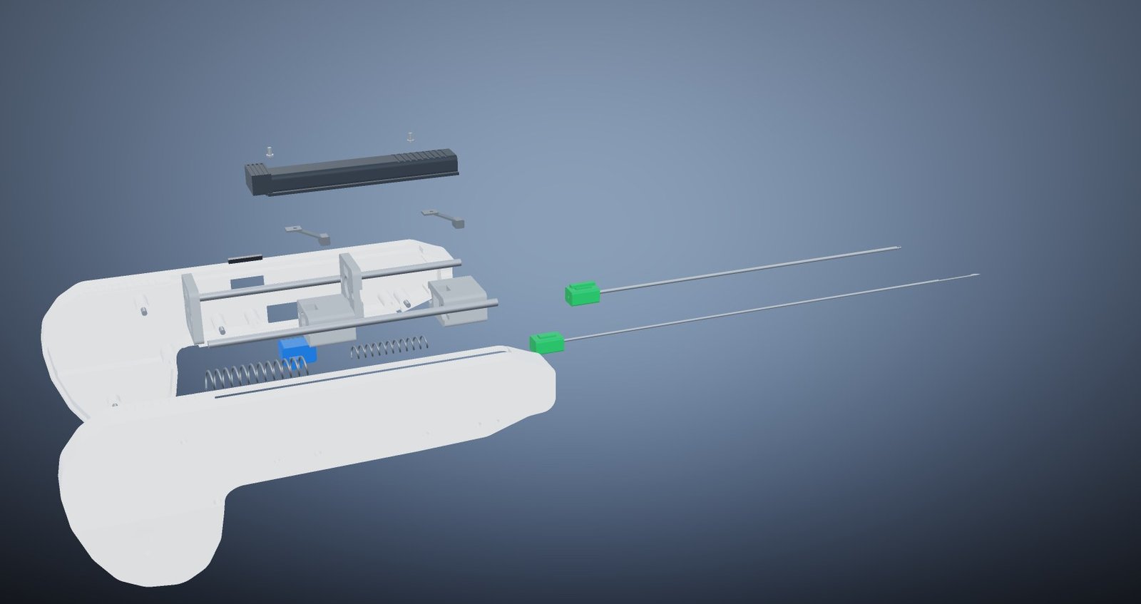
- Assembly: 31 bodies, clamshell split on the instrument centreline
How the instrument works
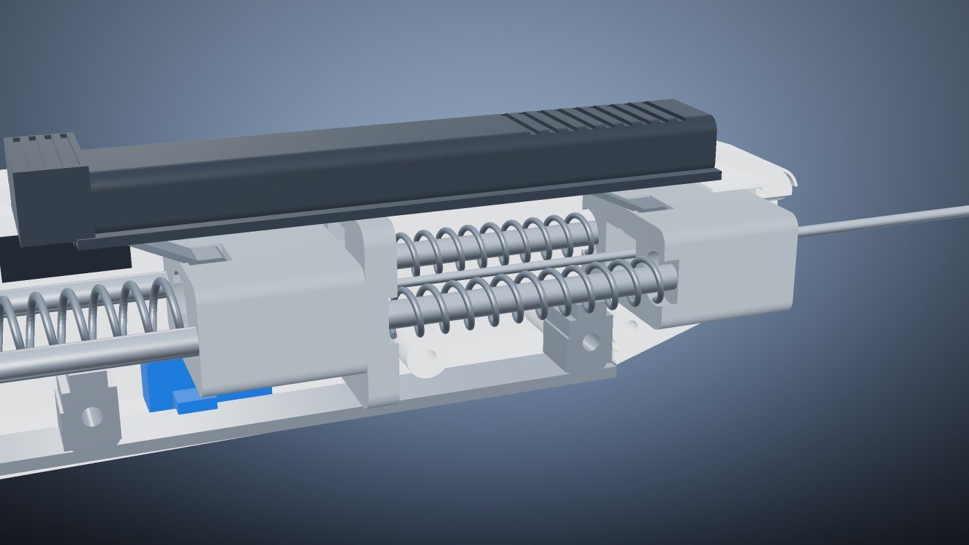
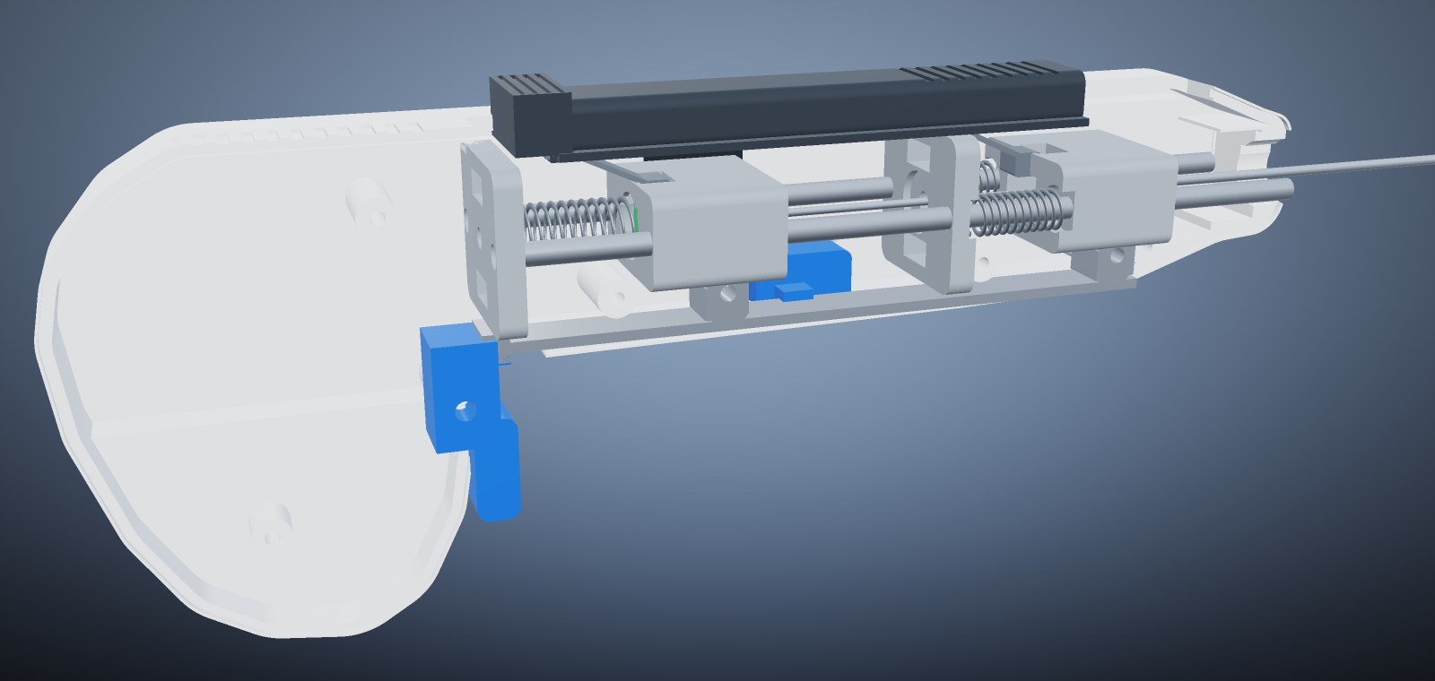
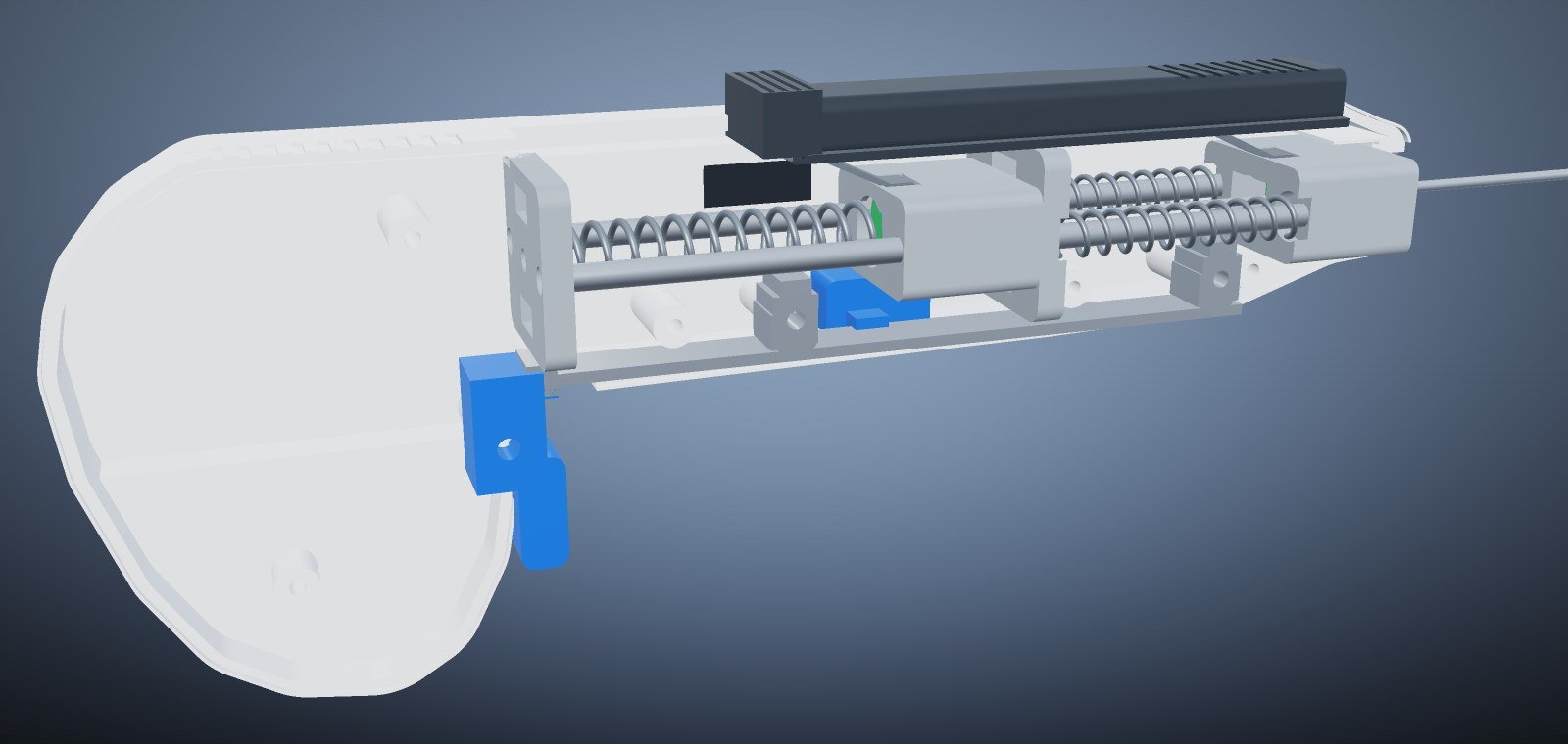
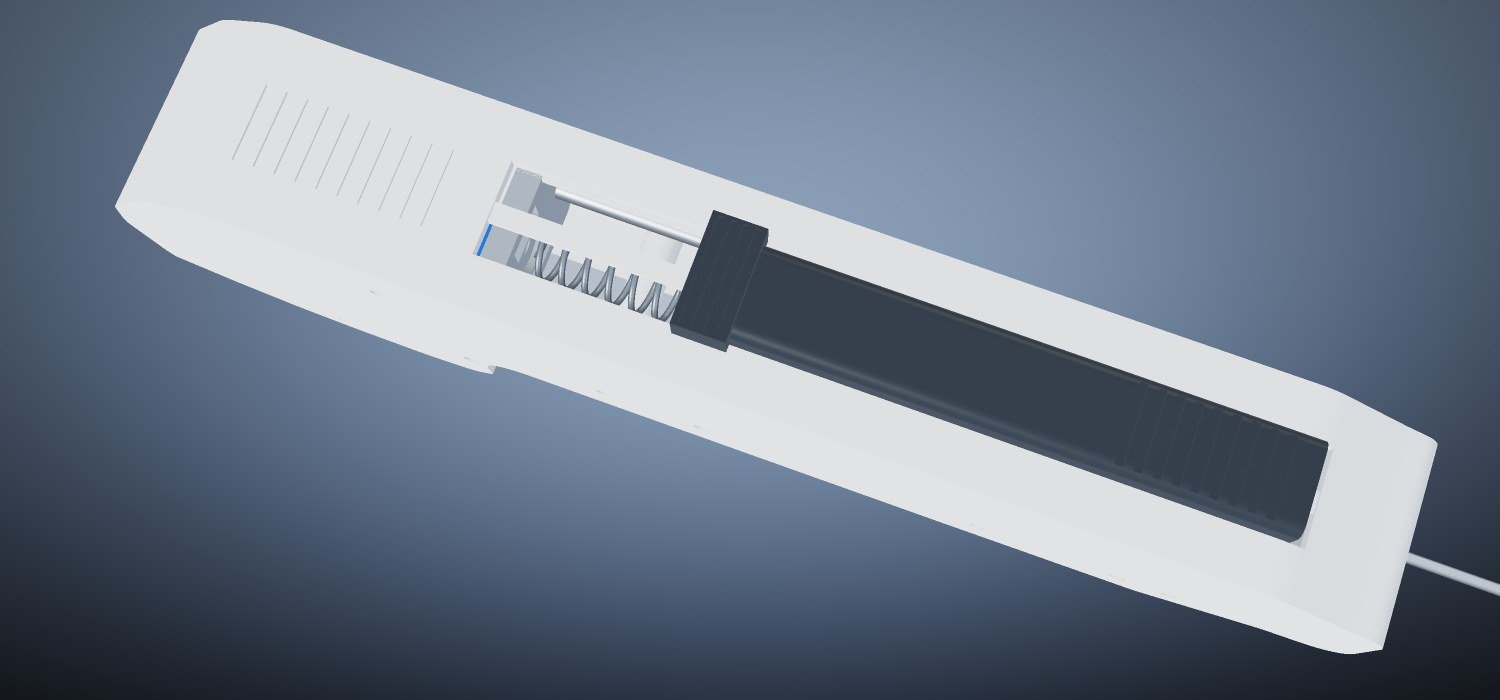
- Cocking. A thumb slide retracts two independent spring trains over 26 mm of travel. Leaf-sprung drive pawls ratchet over each carriage as its trip latch catches, so the operator hears and feels the instrument arm.
- Two audible stages. The stylet carriage latches at 22 mm and the cannula carriage at 26 mm, which is what makes the arming sequence unambiguous in use.
- Stylet fires. One trigger pull advances a single sear bar. Its first cam releases the stylet trip latch; the stylet flies 26 mm and opens the specimen notch inside tissue.
- Cannula follows 3.5 ms later. The second cam sits 0.6 mm further back, so the cannula latch releases after the stylet. The cannula flies 22 mm over the notch and shears a full-length core.
- Capture. The core is sealed inside the needle for withdrawal. Everything that touches the patient is on the disposable cartridge — the instrument body never enters the sterile field.
Two springs, one trigger
A single-spring instrument couples the stylet and the cannula, so friction on one affects the other. The CB-16 separates them. A central Ø9 spring drives the stylet through 26 mm at 1.45 N/mm; a balanced pair of Ø6.5 springs on the guide rails drives the cannula through 22 mm at 0.92 N/mm each. The cutting stroke is therefore unaffected by stylet friction, and the only thing that sets the delay between them is 0.6 mm of cam offset on the sear bar.
Assembly and materials
The reusable body is a two-part clamshell in medical-grade PC/ABS, split on the instrument centreline. Inside it, two hardened guide rails carry the stylet and cannula carriages; the trigger, safety slider and cocking slide are acetal; the latches, sear bar, rails and screws are hardened 440C. The disposable is a keyed dual-needle cartridge loaded through the nose receiver bore and captured by the two carriages.
| Group | Parts | Material |
|---|---|---|
| Housing | Left and right clamshell halves | PC/ABS medical grade, ISO 10993-5/-10 |
| Status window | Window lens, needle hubs | Polycarbonate, EtO sterilisable |
| Controls | Trigger, safety slider, cocking slide | POM-C acetal copolymer |
| Structure | Bulkheads, stylet and cannula carriages | PA66-GF30 |
| Precision | Rails, latches, sear bar, rivets, screws | 440C stainless, 56 HRC, Ra 0.2 |
| Springs | Stylet spring, paired cannula springs, drive pawls | AISI 302 spring steel, shot-peened |
| Needles | Cutting cannula and notched stylet | AISI 304 stainless, electropolished |
Detail design
Drawing, datums and tolerances
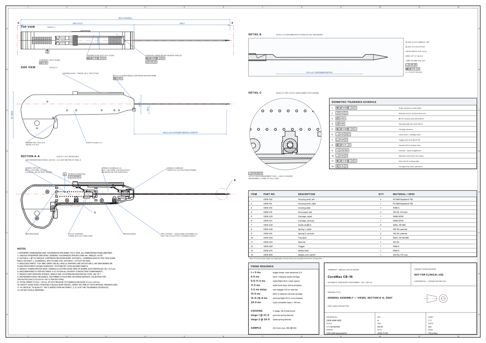
The general assembly sheet, CB16-ASM-0001 Rev A, is an ISO A1 drawing generated from the same model as the renders. It carries a four-datum scheme and twelve scheduled characteristics.
| Datum | Feature |
|---|---|
| A | Ø11 H7 needle-cartridge receiver bore in the nose |
| B | Common axis of the two Ø3.5 guide rails |
| C | Clamshell split plane |
| D | Stylet OD axis |
The controlled characteristics include rail bore position ⌖Ø0.05 Ⓜ A C, rail parallelism ∥0.03 A, receiver bore cylindricity ⌭0.015, split-plane flatness ⏥0.08, latch-tooth profile ⌓0.05 B C and cannula coaxiality ◎Ø0.10 A. Items 1, 3, 8 and 9 are flagged for 100% inspection.
Engineering checks
| Check | Result |
|---|---|
| Firing cycle | 28 ms total, against a < 30 ms target |
| Sequencing delay | 3.5 ms, from a 0.6 mm cam offset on the sear bar |
| Stylet throw | 26.0 mm, enough to open the full 20 mm notch |
| Cannula throw | 22.0 mm cutting stroke |
| Spring trains | Ø9 × 1.45 N/mm stylet; paired Ø6.5 × 0.92 N/mm cannula |
| Solid model | 31 of 31 bodies valid, single-solid and watertight, including after a STEP round trip |
| Material volume | 110.22 cm³ home, 109.94 cm³ cocked — the difference is exactly the compressed springs |
Interactive 3D model
Drag to orbit and scroll to zoom. Switch to cutaway, explode the assembly, or scrub the firing sequence millisecond by millisecond to watch the carriages, springs and latches work.
Deliverables
- STEP AP214 assembly in both home and fully cocked states, with part names and colours
- glTF binary, 48.5k triangles, with named parts for real-time viewing
- 31 per-part STL bodies
- ISO A1 general assembly drawing with GD&T, as vector SVG, print-ready PDF and 4200 px raster
- 13 PBR concept renders, plus a Blender setup for turntable, exploded and firing animations
- Per-body validation report and a manifest of parts, materials and kinematics
- An interactive 3D viewer with a scrubbable firing sequence, embedded in this page
Known limits of this concept
- Not prototyped, not analysed by FEA and not clinically evaluated. Spring rates and timings are design intent computed from geometry, not measured.
- Drive pawls are modelled as separate riveted leaf springs. A production design would most likely integrate them into the slide moulding as living hinges.
- Moulding draft is called out in the drawing notes but is not yet modelled on the housing walls.
- No tolerance stack-up has been run. The engagement depth of the trip latches, 2.4 mm minimum at full cock, is the first thing a stack-up should confirm.